CS Instruments Thermal Mass Flowmeters
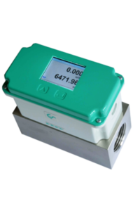
VA 525 – Compact in-line flow sensor
Compress Air Thermal Mass Flow Meter
Flow sensor with integrated flow straightener / no inlet sections necessary
The newly developed VA 525 combines modern digital interfaces for connection to an energy monitoring system with a small, compact design. Due to its reasonable price and modern digital interfaces this compact in-line flow sensor is used when many machines (compressed air consumers) are to be integrated as easily as possible into an energy monitoring network.
Special advantages of the flow sensor VA 525
- Compact, small design – for use in machines, behind maintenance unit at the end user
- Optionally with classic analogue signals (4…20 mA and pulse) or digital interfaces such as Modbus RTU, Ethernet (also PoE), M-Bus
- All interfaces are programmable via the display
- Compact, small design – for use in machines, behind maintenance unit at the end-user
- Optionally with classic analog signals(4…20 mA and pulse) or digital interfaces such as Modbus RTU, Ethernet (also PoE), M-Bus
- All interfaces are programmable via the display
- Current consumption in m³/h, l/min,…
- Total consumption (meter reading) in m³, l, kg
- Temperature measurement
- Optional: pressure measurement
- Easy installation in existing piping through integrated measuring block (suitable for 1/4 ̋, 1/2“, 3/4 ̋, 1“, 1 ¼ ̋, 1 ½“ or 2″ lines)
- Display values can be rotated 180° in the display, e. g. when installing overhead
| Parameters | m³/h, l/min (1000 mbar, 20 °C) in case of compressed air resp. Nm³/h, Nl/min (1013 mbar, 0°C) in case of gases |
| Units adjustable via keys at a display | m³/h, m³/min, l/min, l/s, ft/min, cfm, m/s, kg/h, kg/min, g/s, lb/min, lb/h |
| Sensor | Thermal mass flow sensor |
| Meas medium | Air, gases |
| Gas types over CS Service Software or CS Datalogger adjustable | Air, nitrogen, argon, CO2, oxygen |
| Accuracy (f. M. = from the measured value) (f. E. = from end value) | ± 1,5 % of m. v. ± 0,3 % of f. s. By request: ± 1 % of m. v. ± 0,3 % of f. s. or ± 6 % of m. v. ± 0,5 % of f. s. |
| Pressure measurement | 0…16 bar, accuracy: 1% |
| Operating temp. | -30…80 °C |
| Operating pressure | Up to 16 bar |
| Digital output | RS 485 interface (Modbus RTU), M-Bus (optional) Ethernet interface or PoE |
| Analog output | 4…20 mA for m³/h resp. l/min |
| Pulse output | 1 pulse per m³ or per liter galvanically isolated. Pulse value adjustable on the display. Alternatively, the pulse output can be used as an alarm relay. |
| Power supply | 18…36 VDC, 5 W |
| Burden | < 500 Ω |
| Housing | Polycarbonate (IP 65) |
| Meas. section | Aluminum |
Mounting thread meas. section: | G 1/4“ to G 2“ (BSP British Standart piping) resp. 1/2“ to 2“ NPT-thread |
| Mounting position: | Any |
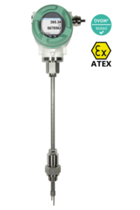
VA 550 – Flow meter for heavy duty industrial applications
Compress Air Thermal Mass Flow Meter
The immersion flow meter VA 550 is the ideal flow sensor for installation into existing compressed air resp. gas lines from 3/4“ up to DN 500.
Special mechanical features:
- Robust impact-proof aluminum die cast housing for the outdoor area IP 67
- All medium-touching parts made from stainless steel 1,4571
- As immersion sensor suitable for 3/4“ up to DN 500
- On request with ATEX approval ATEX II 2G Ex d IIC T4
- On request with DVGW approval for natural gas (up to 16 bar)
- Pressure range up to 50 bar, special version up to 100 bar
- Temperature range up to 180 °C
- No moving parts, no wearout
- Sensor tip very robust, easy to clean
- Easy mounting and dismounting under pressure via 1/2“ ball valve
- Housing twistable, display twistable by 180°
- Safety ring for mounting and dismounting under pressure
- Depth scale for precise installation
Special measurement technology features:
- 4 values in the display: Nm³/h, Nm³, Nm/s, °C units freely adjustable
- Min/max values and daily/hours/minutes average values freely adjustable
- All measured values, settings like gas type, inner diameter, serial number and so on retrievable via Modbus RTU
- Comprehensive diagnosis functions readable at the display or remote access via Modbus like e. g. exceeding of max/min values °C, calibration cycle, error codes, serial number, all parameters readable and adjustable
- Notification in case of exceeding of the calibration cycle
- Standard version accuracy 1.5 % of m.v. ± 0.3 % of f.s.
- Precision version accuracy 1.0 % of m.v. ± 0.3 % of f.s. up to
- 40 calibration points with certificate
- Measuring span of 1 : 1000 (0.1 up to 224 m/s)
- Configuration and diagnosis via display, hand-held instrument
- PI 500, PC service software on-site
- Gas type (air, nitrogen, oxygen, argon and so on) freely adjustable
- Reference conditions °C and mbar/hPa freely adjustable
- Zero-point adjustment, leak flow volume suppression
- Pressure loss negligible
- Flow measurement in both directions via flow direction switch
Measuring range
A1 Standard version (92,7 m/s)
A2 Max version (185 m/s)
A3 High-speed version (224 m/s)
A4 Low-speed version (50 m/s)
Screw-in thread
B1 G 1/2″ male thread
B2 1/2″ NPT male thread
B3 PT 1/2” male thread
Installation length / shaft length
C1 220 mm
C2 300 mm
C3 400 mm
C4 500 mm
C5 600 mm
C6 700 mm (not with ATEX)
C7 160 mm
C8 1000 mm (not with ATEX)
C9 1500 mm (not with ATEX)
Display option
D1 with integrated display
D2 without display
Signal outputs / bus connection option
E1 2 units 4…20 mA analogue output (electrically isolated),
pulse output, RS 485 (Modbus-RTU)
E2 Profi bus DP, 1 x 4…20 mA analogue output (not electrically isolated), pulse output, RS 485 (Modbus-RTU)
E4 1 x 4…20 mA analogue output (not electrically isolated),
pulse output, RS 485 (Modbus-RTU)
E5
Ethernet interface (Modbus / TCP), 1 x 4…20 mA analogue output (not electrically isolated), pulse output, RS
485 (Modbus-RTU)
E7 2 units 4…20 mA analogue output passive, pulse output
RS 485 (Modbus-RTU)
E8 M-Bus, 1 x 4…20 mA analogue output (not electrically
isolated), pulse output, RS 485 (Modbus-RTU)
E9
Ethernet interface PoE (Power over Ethernet) (Modbus/
TCP), 1 x 4…20 mA analogue output (not electrically
isolated), pulse output, RS 485 (Modbus-RTU)
Adjustment / calibration
F1 No real gas adjustment – gas type confi guration per gas
constant
F2 Real gas adjustment in the gas type selected below
Gas type
G1 Compressed air
G2 Nitrogen (N2)
G3 Argon (Ar)
G4 Carbon dioxide (CO2)
G5 Oxygen (O2)
G6 Nitrous oxide (N2O)
G7 Natural gas (NG)
G8 Helium (He) (real gas adjustment F2 required)
G9 Propane (C3H8) (real gas adjustment F2 required)
G10 Methane (CH4)
G11 Biogas (methane 50% : CO2 50%)
G12 Hydrogen (H2) (real gas adjustment F2 required)
G90 Further gas / please indicate gas type (on request)
G91 Gas mixture / please indicate mixture ratio (on request)
Maximum pressure (more than 10 bar high-pressure protection required!)
H1 50 bar
H2 100 bar
H3 16 bar
Surface conditon
I1 standard version
I2 special cleaning – oil and grease free (e.g. for oxygen
applications and so on)
I3 Silicone-free version including special cleaning oil- and
grease-free
Accuracy class
J1 ± 1.5% of the measured value ± 0.3% f.s. (standard)
J2 ± 1% of the measured value ± 0.3% f.s. (precision)
Maximum gas temperature on the sensor tip
K1 up to 120 °C gas temperature (only for ATEX version)
K2 up to 180 °C gas temperature (standard)
Approvals
L1 Non-explosive area – no approval
L2 ATEX II 2G Ex db IIC T4 Gb
ATEX II 2D Ex tb IIC T90 °C, Db
L3 DVGW approval for natural gas (max. pressure 16 bar)
Reference standard
M1 20 °C, 1000 mbar
M2 0 °C, 1013.25 mbar
M3 15 °C, 981 mbar
M4 15 °C, 1013.25 mbar
Special measuring range
R1 Special measuring range (please specify when placing
order)
TECHNICAL DATA VA 550
Measuring range VA 550: up to 50 Nm/s, low-speed version*
up to 92.7 Nm/s, standard version*
up to 185 Nm/s, max. version*
up to 224 Nm/s, high-speed version*
* Measuring range Nm³/h for diff erent
pipe diameters and gases, see table
measuring ranges fl ow
* All measured values related to DIN
1343 standard conditions 0° and 1013
mbar ex works
Accuracy:
Accuracy class
(o. M. V. = of measured
value)
(o. F. S. = of full scale)
± 1.5 % of m.v. ± 0.3 % of f.s.
on request:
± 1.0 % of m.v. ± 0.3 % of f.s.
Accuracy indications: relative to ambient temperature 22 °C ±
2 °C, system pressure 6 bar
Repeatability: 0.25 % of m.v. in case of correct
mounting (mounting aid, position, inlet
section)
Measuring principle: Thermal mass flow sensor
Response time: t 90 < 3 s
Operating temperature range sensor tube/display unit:
-40…180 °C standard version, sensor
tube
-20…70 °C display unit
-20…120 °C for ATEX version
Adjustment possibilities
via display, external
hand-held device PI 500,
PC Service Software,
remote diagnosis:
Nm³/h, Nm³/min, Nl/min, l/s, ft/min,
cfm, kg/h, kg/min, inner diameter,
reference conditions ° C/° F, mbar/hPa,
zero point correction, leak fl ow volume
suppression, scaling analogue output
4…20 mA, pulse/alarm, error codes etc.
Outputs: Standard: 1 x 4…20 mA analogue
output (electrically not isolated), pulse
output,
RS 485 (Modbus-RTU)
Optional: 2 x 4…20 mA active, Modbus
TCP, HART, Profi bus DP, Profi net,
M-Bus
Burden: < 500 ohm
Additional average value calculation:
for all parameters freely adjustable
from 1 minute up to 1 day, e. g. 1/2
hours average value, average day
value
Protection class: IP 67
Material: Die-cast aluminum housing, sensor
tube stainless steel 1.4571
Screw-in thread: G 1/2″ ISO 228, NPT 1/2″, R 1/2″,
PT 1/2″
Operating pressure VA 550:
50 bar, in special version 100 bar
(with DVGW approval max. 16 bar)
Power supply: 18…36 VDC, 5 W
Approval: ATEX II 2G Ex db IIC T4 Gb,
ATEX II 2D Ex tb IIC T90 °C, Db,
DVG
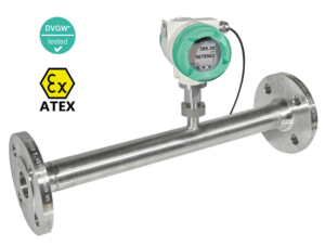
VA 570 – Flow meter with integrated measuring section
Compress Air Thermal Mass Flow Meter
Flow meter VA 570 is supplied with an integrated measuring section for compressed air and gas pipes. The measuring sections are available in flanged version or with R resp. NPT thread.
A special feature is the removable measuring head. So the measuring unit can be removed easily and quickly for calibration or cleaning purposes without having to dismount the measuring section intricately. During this period the measuring section is sealed by a closing cap (accessory).
The screwing with centring device ensures that the sensor is positioned accurately in the centre when screwing it into the measuring section furthermore it grants an exact positioning in the flow direction. This avoids unnecessary measuring faults.
Robust design for demanding industrial applications
The new flow meters VA 550/ 570 work according to the calorimetric measuring principle. Therefore an additional temperature and pressure compensation is not necessary.
Due to its robust design, the aluminum die cast housing, the robust sensor tip made from stainless steel 1,4571, the new VA 550/ 570 are suitable for demanding industrial applications. An ATEX version is available for applications in explosive areas. For flow measurement e. g. of natural gas there is a version with a DVWG admission.
Contrary to the previously used bridge circuit the newly developed evaluation electronics records all measured values digitally. This allows very precise and fast measurements with a wide temperature range of up to 180 °C (resp. 350 °C). The measuring span is 1…1000 and enables therefore measurements in very low as well as in very high flow speeds of up to 224 m/s.
Simple operation and flexible interface
VA 550/ 570 has an integrated Modbus output as a standard with which all parameters like Nm³/h, Nm³, Nm/s, Nl/min, Nl/s, kg/h, kg/min, ft/min, °C etc. can be transferred. All parameters can be adjusted directly at the instrument (via display) or via the PI 500 hand-held measuring instrument resp. the Service Software. Of course there are also 2 x 4…20 mA analogue outputs available for flow and temperature and a galvanically isolated pulse output for the total consumption.
A remote diagnosis can be carried out via Modbus and all relevant parameters can be checked and changed if necessary. So it is possible to change e. g. the gas type, the inner diameter, the scaling and so on or the zero point resp. the leak flow volume suppression in case of changed process conditions.
Via remote diagnosis and status update e. g. temperature exceeding, failures of the flow sensor or the calibration date can be determined.
TECHNICAL DATA VA 570
Measuring range VA 570: up to 50 Nm/s, low-speed version*
up to 92.7 Nm/s, standard version*
up to 185 Nm/s, max. version*
up to 224 Nm/s, high-speed version*
* Measuring range Nm³/h for different
pipe diameters and gases, see table
measuring ranges flow
* All measured values related to DIN
1343 standard conditions 0° and 1013
mbar ex works
Accuracy:
Accuracy class
(o. M. V. = of measured
value)
(o. F. S. = of full scale)
± 1.5% of m.v. ± 0.3 % of f.s.
on request:
± 1.0% of m.v. ± 0.3 % of f.s.
Accuracy indications: relative to ambient temperature 22 °C
± 2 °C, system pressure 6 bar
Repeatability: 0.25% of m.v. in case of correct
mounting (mounting aid, position, inlet
section)
Measuring principle: Thermal mass flow sensor
Response time: t90 < 3 s
Operating temperature
range sensor tube/display unit:
-40…180 °C standard version, sensor
tube
-20…70 °C display unit
-20…120 °C for ATEX version
Adjustment possibilities
via display, external
hand-held device PI 500,
PC Service Software,
remote diagnosis:
Nm³/h, Nm³/min, Nl/min, l/s, ft/min,
cfm, kg/h, kg/min, inner diameter,
reference conditions ° C/° F, mbar/
hPa, zero point correction, leak flow
volume suppression, scaling analogue
output 4…20 mA, pulse/alarm, error
codes etc.
Outputs: Standard: 1 x 4…20 mA analogue
output (not electrically isolated), pulse
output, RS 485 (Modbus-RTU)
Optional: 2 x 4 … 20 mA active,
Modbus TCP, HART, Profibus DP,
Profinet, M-Bus
Burden: < 500 Ohm
Additional average value calculation:
for all parameters freely adjustable
from 1 minute up to 1 day, e. g. 1/2
hours average value, average day
value
Protection class: IP 67
Material: Die-cast aluminum housing, sensor tube stainless steel 1.4571
Operating pressure: 16 bar, in special version 40 bar
Power supply: 18…36 VDC, 5 W
Approval: ATEX II 2G Ex db IIC T4 Gb,
ATEX II 2D Ex tb IIC T90 °C, Db,
DVGW
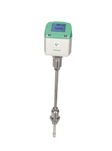
VA 500 – Flow sensor for compressed air and gases
Compress Air Thermal Mass Flow Meter
Contrary to the previously used bridge circuit the newly developed evaluation electronics of our flow sensor records all measured values digitally. This leads to a better accuracy also in case of large measuring spans of 1:1000.
Special features of flow sensor VA 500:
- RS 485 interface, Modbus-RTU as a standard
- Option integrated display for m³/h and m³
- Usable from 1/2“ to 12“ (DN 300)
- Easy installation under pressure
- 4…20 mA analogue output for m³/h resp. m³/min
- Pulse output for m³
- Inner diameter adjustable via keypad
- Consumption counter resettable
- Adjustable values at the display of the flow sensor: Reference conditions, °C and mbar, 4…20 mA scaling, pulse weight
TECHNICAL DATA VA 500
Parameters: m³/h, l/min (1000 mbar, 20 °C) in
case of compressed air or Nm³/h,
Nl/min (1013 mbar, 0 °C) in case of
gases
Units adjustable via keys
at display:
m³/h, m³/min, l/min, l/s, ft/min, cfm,
m/s, kg/h, kg/min, g/s, lb/min, lb/h
Adjustable via keypad: Diameter for volume flow calculation, counter resettable
Sensor: Thermal mass flow sensor
Measured medium: Air, gases
Gas types are adjustable over CS service software or CS data logger:
Air, nitrogen, argon, helium, CO2,
oxygen, vacuum
Measuring range:
Accuracy:
(m.v.: of meas. value) (f.s.:
of full scale)
± 1.5% of m.v. ± 0.3 % of f.s.
on request:
± 1% of m.v. ± 0.3% of f.s.
Operating temperature: -30…110 °C sensor tube
-20…+70 °C housing
Operating pressure: -1…50 bar (for pressure > 10 bar
– order additional high-pressure
protection)
Digital output: RS 485 interface, (Modbus-RTU),
optional: Ethernet interface PoE,
M-Bus
Analogue output: 4…20 mA for m³/h or l/min
Pulse output: 1 pulse per m³ or per litre electrically isolated. Pulse weight can be
set on the display. Alternatively, the
pulse output can be used as an
alarm
Supply: 18…36 VDC, 5 W
Burden: < 500 Ω
Housing: Polycarbonate (IP 65)
Sensor tube: Stainless steel, 1.4301
Installation length 220 mm, Ø
10 mm
Mounting thread: G 1/2″, G 1/2″ NPT male thread
Ø housing: 65 mm
Mounting position: any
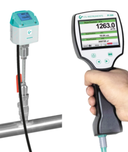
PI 500 for portable flow measurement
PI 500 – Portable Flow Meter
Compress Air Thermal Mass Flow Meter
The portable flow meter PI 500 is an all-purpose hand-held measuring instrument for many compressed air and gas applications in industry like e.g.:
- Flow measurement
- Pressure-/ vacuum measurement
- Temperature measurement
- Moisture/ dew point measurement
The graphic indication of coloured measurement curves is inimitably. Up to 100 million measured values can be stored with date and name of measuring site. The measured values can be transferred to the computer by means of a USB stick. The data can be comfortably evaluated with the CS Soft Basic software. Measured data and service reports can be issued easily and quickly. The following sensors can be connected to the freely configurable sensor input of PI 500:
- Pressure sensors (high and low pressure)
- Flow sensors, VA 500 / VA 520
- Temperature sensors Pt 100, Pt 1000 / 4…20 mA
- Dew point sensors FA 510 / FA 515
- Effective power meters
- Opitonal third-party sensors with the following signals: 0…1/10 V, 0/4…20 mA, Pt 100, Pt 1000, pulse, Modbus
The special features of PI 500
- Universal sensor input for lots of common sensor signals
- Internal rechargeable Li-Ion batteries (approx. 12h continuous operation)
- 3.5″ graphic display / easy operation via touch screen
- Integrated data logger for storage of the measured values
- USB interface for reading out via USB stick
- International: Up to 8 languages selectabel
Technical Data | |
| Display | 3.5 ̋ touchpanel TFT transmissive, graphics, curves, statistics |
| Interface | USB interface |
| Power supply for sensors | Output voltage: 24VDC ± 10% |
| Output current: 120 mA in continuous operation | |
| Power supply | Internal rechargeable Li-Ion batteries, charging time approx. 4 h, PI 500 continuous operation> 4h depending on power consumption for ext. sensor |
| Power adapter | 100 – 240 VAC / 50 – 60 Hz, 12 VDC – 1A, safety class 2 only for use in dry rooms |
| Dimensions | 82 x 96 x 245 mm |
| Housing material | PC/ABS |
| Weight | 450 g |
| Operating temperature | 0…50°C Ambient temperature |
| Storage temperature | -20 bis +70°C |
| EMC | DIN EN 61326 |
| Sensor input | For connection of pressure and temperature sensors, current clamps, external sensors with 4 … 20 mA, 0-10V, Pt 100, Pt 1000, Modbus |
| Memory Size | 8 GB – Memory card standard |
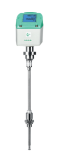
VD 500 – Flow meter for FAD measurement
Compress Air Thermal Mass Flow Meter
For measuring downstream of the compressor in wet air up to +200 °C
The integrated, precise differential pressure sensor measures the differential pressure/ dynamic pressure at the sensor tip. The pressure depends on the respective gas velocity. The flow is therefore easy to determine by means of the pipe diameter.The additional measurement of temperature and absolute pressure and calculation of the relevant density means that measuring can be carried out for various gases, a wide variety of temperatures and pressures.
TECHNICAL DATA VD 500
Measuring range: up to 224 m/s / 600 m/s
Measured medium: Air, non-aggressive gases
Accuracy:
(m.v.: of meas. value) (f.s.: of
full scale)
± 1.5% of m.v. ± 0.3% of f.s.(20…224 m/s)
± 1.5% of m.v. (> 224 m/s)
Measuring principle: Differential pressure
Measuring span: 1:10
Response time: t 99: < 1 sec.
Temperature of the medium: -30 °…+180 °C
Operating pressure: Max. 20 bar
Ambient temperature: -30 °…+70 °C
Screw-in thread: G 1/2″, ISO 228
Power supply: 18…36 VDC, 5 W
Signal outputs: As standard:
RS 485 (Modbus-RTU), 4…20 mA, pulse
Optional:
Ethernet Interface (PoE), M-Bus
Field of application:
- Measurement downstream of the compressor
- Measurement at high temperatures
- Measurement of fast processes
Benefits at a glance:
- Particularly suitable for extremely high flow rates
- Extremely fast response time: 100 ms
- Flow, total consumption, temperature and pressure
- Measurement at high temperatures, max. temperature 200 °C
- Measurement in various gases by selecting gas type, on request
- Can be used in pipes from DN 20 to DN 500
- Installation via 1/2″ ball valve under pressure
- RS 485 interface (Modbus-RTU), 4…20 mA, pulse output as standard
Typical applications:
- FAD measurement of compressors
- Compressed air audits
- Efficiency measurement of compressed air systems
Installation conditions:
- Behind proper working water separator
- In horizontal pipes (recommended) or in vertical pipes
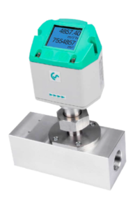
VA 521 – Compact Inline flow meter for compressed air and other gas types
Compress Air Thermal Mass Flow Meter
Flow sensor with integrated flow straightener / no inlet sections necessary
The newly developed VA 521 combines modern digital interfaces for connection to an energy monitoring system with a small, compact design. The VA 521 is always used when many machines (compressed air consumers) are to be integrated into an energy monitoring network.
The high-contrast, integrated display also displays the current values rotated by 180° if desired (very useful for overhead installation). Depending on the configuration, two of the following values can be displayed:
- Current consumption in m³/h, l / min, …
- Total consumption (meter reading) in m³, l, kg
- Temperature measurement
The advantages at a glance:
- Screw thread for easy installation in existing piping through integrated measuring block (suitable for 1/2“, 3/4 ̋, 1“, 1 1⁄4 ̋, 1 1⁄2“ or 2″ lines)
- Compact, small design – for use in machines, behind maintenance unit at the end user
- All interfaces are programmable via the display
- Modbus RTU output
- 4…20mA analog output for actual flow
- Pulse output total flow (counter reading), galvanically isolated. Optionally M-Bus, Ethernet-Interface, or PoE
TECHNICAL DATA VA 521
Parameters: m³/h, l/min (1000 mbar, 20 °C) in case
of compressed air or Nm³/h, Nl/min
(1013 mbar, 0 °C) in case of gases
Units adjustable via keys at display:
m³/h, m³/min, l/min, l/s, ft/min, cfm, m/s,
kg/h, kg/min, g/s, lb/min, lb/h
Sensor: Thermal mass flow sensor
Measured medium: Air, gases
Gas types are adjustable over CS service software or CS data logger:
Air, nitrogen, argon, CO2, oxygen
Accuracy:
(o. M. V. = of measured
value)
(o. F. S. = of full scale)
± 1.5% of m.v. ± 0.3 % of f.s.
on request:
± 1% of m.v. ± 0.3% of f.s.
Operating temperature: -30…80 °C
Operating pressure: Up to 16 bar, optionally 40 bar
Digital output: RS 485 interface, (Modbus-RTU), optional M-Bus, Ethernet interface or PoE
Analogue output: 4…20 mA for m³/h or l/min
Pulse output: 1 pulse per m³ or per litre electrically isolated. Pulse weight can be set on the display.
Alternatively, the pulse output can be used as an alarm relay.
Supply: 18…36 VDC, 5 W
Burden: < 500 Ω
Housing: Polycarbonate (IP 65)
Measuring section: Aluminium, 316L
Connection thread of measuring sections:
G 1/2″ to G 2″ (BSP British Standard
Piping) or 1/2″ to 2″ NPT thread
Mounting position: any
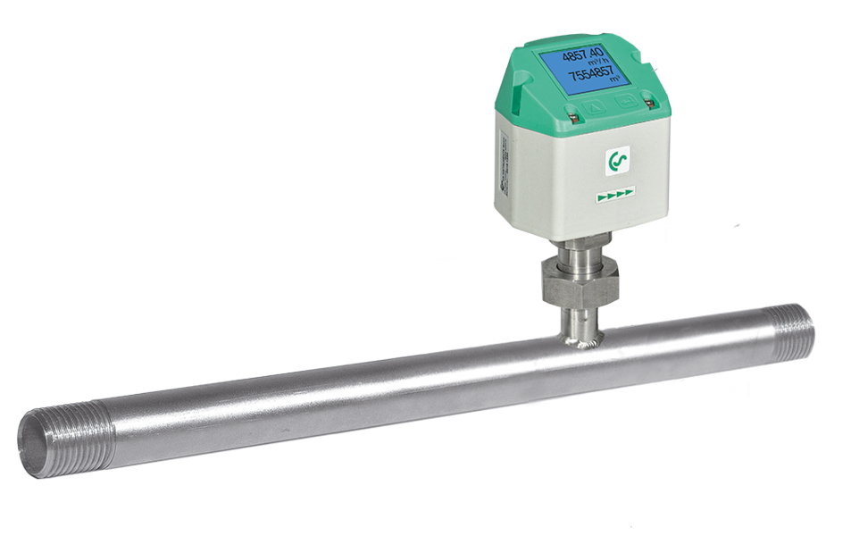
VA 520 – Flowmeter with integrated measuring section
Mass Flow Meter for Compressed Air and Gas
Our affordable mass flow meter for compressed air and gases works according to the approved calorimetric measuring principle. An additonal pressure and temperature compenstation is not necessary. Contrary to the previously used bridge circuit the newly developed evaluation electronics records all measured values digitally. This enables very precise and fast measurements.
Due to the new evaluation electronics, all VA 520 models have an integrated Modbus output as a standard. So all parameters can be easily transferred via Modbus.
Due to its compact design it is possible to monitor all compressed air systems from the compressor to the smallest compressed air tool (1/4“ to 2 inch) with the new mass flow sensor VA 520. VA 500 flow sensors are available for larger pipe diameters from DN 50 to DN 300. Apart from compressed air also other gases like e.g. nitrogen, oxygen and CO2 can be measured.
Application-technological features of the flow meters VA 520:
• Digital interfaces such as Modbus-RTU, Ethernet (PoE) and M-Bus enable connection to higher-level systems such as energy management systems, building management systems, PLC,…
• Easy and affordable installation
• Units freely selectable via keys on the display m³/h, m³/min, l/min, l/s, kg/h, kg/min, kg/s, cfm
• Compressed air counter up to 1,999,999,999 m³ can be reset to “zero” via keypad
• Analog output 4…20 mA, pulse output (electrically isolated)
• High measuring accuracy even in the lower measuring range (ideal for leakage measurement)
• Negligibly small loss of pressure
• Calorimetric measuring principle, no additional pressure and temperature measurement necessary, no mechanically moved parts
• Comprehensive diagnostic functions can be read out on the display or remote access via Modbus-RTU such as exceeding max./
min values °C, calibration cycle, error codes, serial number. All parameters can be read out and changed via Modbus
TECHNICAL DATA VA 520
Parameters: m³/h, l/min (1000 mbar, 20 °C) in case of compressed air or Nm³/h, Nl/ min (1013 mbar, 0 °C) in case of gases
Units adjustable via keys at display:
m³/h, m³/min, l/min, l/s, ft/
min, cfm, m/s, kg/h, kg/
min, g/s, lb/min, lb/h
Sensor: Thermal mass flow sensor
Measured medium: Air, gases
Gas types are adjustable over CS service software or CS data logger:
Air, nitrogen, argon, CO2, oxygen
Accuracy:
(o. M. V. = of measured
value)
(o. F. S. = of full scale)
± 1.5% of m.v. ± 0.3% of
f.s.
on request:
± 1% of m.v. ± 0.3% of f.s.
Operating temperature: -30…80 °C
Operating pressure: -1 to 16 bar optionally up to PN 40
Digital output: RS 485 interface,
(Modbus-RTU), optional:
Ethernet interface PoE), M-Bus
Analogue output: 4…20 mA for m³/h or l/min
Pulse output: 1 pulse per m³ or per litre electrically isolated. Pulse weight can be set on the display.
Alternatively, the pulse output can be used as an alarm relay
Supply: 18…36 VDC, 5 W
Burden: < 500 Ω
Housing: Polycarbonate (IP 65)
Measuring section: Stainless steel, 1.4301 or 1.4571
Process connection: Flange (in acc. with DIN EN 1092-1 or ANSI 150 Ibs or ANSI 300 Ibs)
Mounting position: any
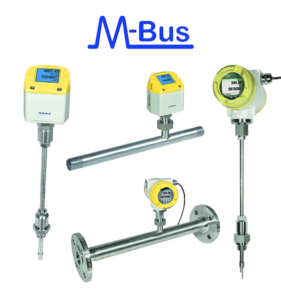
M-Bus – Industrial gas meter
Compressed air and natural gas meters with M-Bus
Our successor product of the proven industrial gas meter with M-Bus gives you all necessary possibilities of digitization of your energy management processes and therefore is the ideal consumption meter for future challenges.
The M-Bus meters have been metrologically improved and completely revised and in addition to the mandatory M-Bus interface also have the following additional outputs and bus systems:
- Modbus RTU
- Modbus TCP or TCP PoE
- Profibus, Profinet
- 4..20 mA and pulse
- Hard (in preparation)
The new flow meters VA 520, VA 500, VA 550 and VA 570 with M-Bus are the ideal consumption and flow measurement devices for natural gas, biogas, methane, nitrogen, argon and carbon dioxide.
Those devices are also ideal for conversion or retrofitting and for new installations of gas meters, compressed air meters, flow meters, etc. to existing or new energy management software according to DIN ISO 50001 and DIN ISO 16247 and building management systems.
Advantages:
- Direct display in Nm3/h, or NI/min and temperature in C°
- Calorimetric measuring principle – no additional pressure and temperature measurement necessary
- High measurement accuracy ¼ to 3 inches
- VA 500 and VA 550 insert version from ½ inch to DN 400 / DN 500
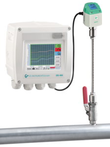
DS 400 – Flow measurement for compressed air and gases
Each factory needs compressed air, however, often it is not realized that compressed air is one of the most expensive types of energy. Therefore, the intelligent use of flow measurement DS 400, holds an enormous potential for saving energy. In most cases the user mainly concentrates on the production, i. e. on the compressors. In order to save energy very often new compressors, control systems or heat recovery systems are installed.
Flow measurement DS 400 consisting of:
Flow sensor VA 500:
- Easy installation and removal under pressure via 1/2″ ball valve
- Several gas types – freely adjustable at DS 400
- Usable from 1/2″ to 12″ DN 300
- Diameter freely adjustable at DS 400
- Output for 4…20 mA for m³/h
- Pulse output for m³ (total flow)
Chart recorder DS 400:
- 3.5″ graphic display with touch screen – shows the progression of the measured values in graphic form
- 2 sensor inputs for flow sensors/ dew point sensors
- USB interface for reading out the data logger via USB stick
- 2 additional sensor inputs for pressure sensors, current meters and so on
- Option: Data logger for 100 million measured values (2 GB SD card)
- Option: Ethernet and RS 485 interface (Modbus protocol)
- Option: Webserver
- Option: CS Soft Basic – comfortable evaluation of the measured data
| Dimensions | 118 x 115 x 98 mm IP 54 (wall housing) 92 x 92 x 75 mm (panel mounting) | |
| Inputs | 2 digital inputs for FA 5xx resp. VA 5xx | |
| Interface | USB | |
| Power supply | 100…240 VAC, 50-60 Hz | |
| Accuracy | Please refer sensor specification | |
| Alarm outputs | 2 relays, (pot.-free) | |
| Options | ||
| Data logger | 100 million measuring values start/stop time, measuring rate freely adjustable | |
| 2 additional sensor inputs | for connection of pressure sensors, temperature sensors, clamp-on ammeters, third-party sensors with 4…20 mA, 0 to 10 V, Pt 100, Pt 1000 | |
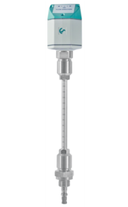
VA 409 – Flow direction switch for compressed air systems
The new thermal flow direction switch VA 409 with direction indication serves for determination of the flow direction of compressed air and gases especially in closed circular pipelines.
By means of VA 409 with flow direction indication the flow direction of the compressed air can be determined quickly and safely. Compared with the former mechanical paddle flow switches VA 409 is able to detect even the smallest changes in the flow direction quickly and without any mechanical movement.
VA 409 Flow direction switch for compressed air systems
The thermal flow direction switch VA 409 with direction indication serves for determination of the flow direction of compressed air and gases, especially in closed circular pipelines.
By means of VA 409 with flow direction indication, the flow direction of the compressed air can be determined quickly and safely. Compared with the former mechanical paddle flow switches VA 409 is able to detect even the smallest changes in the flow direction quickly and without any mechanical movement.
The direction information in form of a potential-free contact (normally closed max. 60 VDC, 0.5 A) is transferred to the consumption sensors VA 500/ VA 520 or to a separate building management system (mbs). Two LEDs show the flow direction.
In connection with 2 consumption sensors VA 500/ VA 520 incoming and outflowing compressed air in closed circular pipelines can be measured precisely.
Special features of the flow direction switch VA 409
- Compact, small design – for use in machines, behind the maintenance unit on the
final consumers - Screw-in thread for easy installation in existing pipelines due to integrated measuring
bloc , Sizes : ¼”, ½” ¾”, 1″ 1 ¼” , 1 ½” and 2″ - Integrated flow straighteners (no inlet runs necessary)
- Integrated display with a presentation of 2 values
- Flow & Consumption,
- Speed & Temperature
- Operation via integrated keyboard
- Units selection, freely selectable : m³/h, m³/min, l/min, l/s, kg/h, kg/min, g/s, lb/min, lb/h
Cfm, m/s,ft/min
- Units selection, freely selectable : m³/h, m³/min, l/min, l/s, kg/h, kg/min, g/s, lb/min, lb/h
- Digital interfaces
- Modbus RTU (RS485)
- Ethernet
- MBus
- Analog interfaces
- 4 – .20mA
- Pulse output galv. insulated.
- Pressure measurement (optional)
Detection range recognition flow direction | < 0.1 m/s referred to auf 20 °C and 1000 mbar |
Measuring principle | calorimetric measurement |
| Sensor | Pt 30/ Pt 700/ Pt 330 |
| Measuring medium | Air, gases |
| Operating temp. | 0…50 °C probe tube |
| -20…70 °C housing | |
| Operating pressure | up to 16 bar |
| Power supply | 24 VDC, 40 mA |
| Power input | Max. 80 mA to 24 VDC |
| Protection class | IP 54 |
| EMV | acc. to DIN EN 61326 |
| Connection | 2 x M12, 5-pole, plug A and plug B |
2 potential-free contacts | 2 x U max. 60 VDC, l max 0,5 A (normally closed); on request: Normally open |
| Housing | Polycarbonate |
| Probe tube | stainless steel, 1,4301, length 160 mm, Ø 10 mm, safety ring Ø 11.5 mm, longer probes on request |
| Mounting thread | G 1/2“ |
| Diameter housing | 65 mm |
| Flow direction | 2 LEDs |

DS 500 – Intelligent chart recorder
Intelligent chart recorder DS 500 for compressed air and gases
Advantages of DS 500 at a glance
- Clear layout: 7″ colour screen with touch panel
- Versatile: Up to 12 optional sensors can be connected
- Suitable for industrial applications: Metal housing IP 65 or panel mounting
- Data avialable though world wide web: Network-compatible and remote transmission via webserver
- Intelligent: Daily/weekly/monthly reports
- Mathematical function for internal calculations
- Totalizer function for analogue signals
- Saves time and costs during installation
Mathematical function for internal calculations
e.g. the typical figures of a compressed air plant:
- costs in € per generated m³ air
- kwh/m³ generated air
- consumption of single lines including summation
Totalizer function for analogue signals
e.g. 0/4…20 mA, 0…10 V. In case of third-party sensors which e.g. only give a 4…20 mA signal for the actual flow in m³/h a total counter reading in m³ can be generated by means of the totalizer function.
| DS 500 | ||
| Dimensions | 280 x 170 x 90 mm, IP 65 | |
| Weight | 7.3 Kg | |
| Material | Die cast metal, front screen polyester | |
| Sensor inputs | 4/8/12 sensor inputs for analogue and digital sensors; freely allocatable | |
| Digital CS sensors for dew point and consumption with SDI interface FA/VA series, digital third-party sensors RS 485 / Modbus RTU, other bus systems realizable on request. | ||
| Analogue CS Sensors for pressure, temperature,clamp-on ammeters preconfigured | ||
| Analogue third-party sensors 0/4…20 mA, 0…1/10/30V, pulse, Pt 100 / Pt 1000, KTY | ||
Power supply for sensors: | 24 VDC, max. 130 mA per sensor, integrated mains unit max. 24 VDC, 25 W. In case of version 8/12 sensor inputs,2 integrated mains units each max. 24 VDC, 25 W. | |
| Interfaces | USB stick, Ethernet / RS 485 Modbus RTU / TCP, SDI other bus systems on request, WEB server optionally,GSM modul(DS 500 Mobile) | |
Memory card | Memory size 4 GB SD memory card standard | |
| Power supply | 100…240 VAC / 50-60 Hz, special version 24 VDC (DS 500) | |
| Color screen | 7“ touch panel TFT transmissive, graphics, curves, statistics | |
| Accuracy | Please see sensor specifications | |
| Operating temperature | 0…50°C | |
| Storage temperature | -20…70°C | |
| Options | ||
| Webserver | ||
| energy and flow report“ statistics, daily/weekly/monthly report | ||

Intelligent mobile chart recorder – DS 500 mobile
If we talk about operational costs of compressed air plants we are actually talking about the energy costs as they make up about 70 to 80 % of the total costs of a compressed air plant. Depending on the size of the plant this means considerable operating costs. Even in smaller plants this may quickly add up to 10 000 to 20 000 € per year. This is an amount which can be considerably reduced – even in case of well operated and maintained plants. For sure this also applies to your compressed air plant! Which actual costs per generated m³ air do you actually have? Which energy is gained due to the waste heat recovery? What is the total performance balance of your plant? How high are the differential pressures of single filters? How high is the humidity (pressure dew point)? How much compressed air is used? By means of the intelligent chart recorder DS 500 mobile and the suitable sensors and meters all these questions can be answered easily. For example by means of a long-term measurement over 7 days, data recording and evaluation at the PC.
Your advantages of DS 500 mobile at a glance
- Easy and clear layout: Very easy operation via 7″ color display with touch panel
- Versatile: Up to 12 sensors/meters connectable also third-party sensors/meters including power supply
- Reliable: Stores all measured values on a memory card, easy reading-out via USB stock possible
- Intelligent energy analysis: Daily/weekly/monthly evaluations mathematic function for internal calculations, e.g. the typical key data of a compressed air plant:
Typical key data of a compressed air plant:
- costs in € per generated m³ air
- kWh/m³ generated air
- flow of single lines including summation
| DS 500 Mobile | ||
| Dimensions | 360 x 270 x 150 mm | |
| Weight | 4,5 kg | |
| Material | Diecast, front foil polyester, ABS | |
| Sensor inputs | 4/8/12 sensor inputs for analogue and digital sensors; freely allocatable | |
| Digital CS sensors for dew point and consumption with SDI interface FA/VA series, digital third-party sensors RS 485 / Modbus RTU, other bus systems realizable on request. | ||
| Analogue CS Sensors for pressure, temperature,clamp-on ammeters preconfigured | ||
| Analogue third-party sensors 0/4…20 mA, 0…1/10/30V, pulse, Pt 100 / Pt 1000, KTY | ||
Power supply for sensors: | 24 VDC, max. 130 mA per sensor, integrated mains unit max. 24 VDC, 25 W. In case of version 8/12 sensor inputs,2 integrated mains units each max. 24 VDC, 25 W. | |
| Interfaces | USB stick, Ethernet / RS 485 Modbus RTU / TCP, SDI other bus systems on request, WEB server optionally,GSM modul(DS 500 Mobile) | |
Memory card | Memory size 4 GB SD memory card standard | |
| Power supply | 100…240 VAC / 50-60 Hz, special version 24 VDC (DS 500) | |
| Color screen | 7“ touch panel TFT transmissive, graphics, curves, statistics | |
| Accuracy | Please see sensor specifications | |
| Operating temperature | 0…50°C | |
| Storage temperature | -20…70°C | |
| Options | ||
| Webserver | ||
| energy and flow report“ statistics, daily/weekly/monthly report | ||
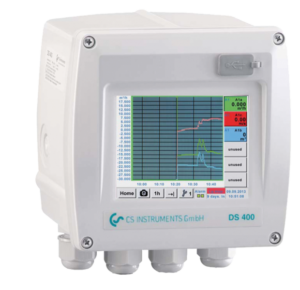
DS 400 – chart recorder
for all relevant parameters of compressed air.
Standard equipment of DS 400
- USB interface
- 3.5″ graphic display with touch screen
- Integrated mains unit for supply of the sensors
- 4…20 mA output of all connected active sensors
- Pulse output (for total consumption) in case of flow sensors
- 2 alarm relays (pot.-free switch-over contacts, max. 230 V, 3 A)
Software options
- Integrated webserver
- Mathematic calculation function
- Totalizer function
Hardware options
- Integrated data logger
- Ethernet / RS 485 interface
- additional sensor inputs (digital or analogue) selectable
| DS 400 | ||
| Dimensions | 118 x 115 x 98 mm IP 54 (wall housing) 92 x 92 x 75 mm (panel mounting) | |
| Inputs | 2 digital inputs for FA 5xx resp. VA 5xx | |
| Interface | USB | |
| Power supply | 100…240 VAC, 50-60 Hz | |
| Accuracy | Please refer sensor specification | |
| Alarm outputs | 2 relays, (pot.-free) | |
| Options | ||
| Data logger | 100 million measuring values start/stop time, measuring rate freely adjustable | |
| 2 additional sensor inputs | for connection of pressure sensors, temperature sensors, clamp-on ammeters, third-party sensors with 4…20 mA, 0 to 10 V, Pt 100, Pt 1000 | |
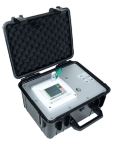
DS 400 mobile
Affordable mobile chart recorder in a case
With integrated data logger and up to 4 sensors connectable, including voltage supply for all sensors.
Your advantages of DS 400 mobile at a glance
- Easy and clear layout: Very easy operation via 3.5″ color display with touch panel
- Versatile: Up to 4 sensors/meters connectable also third-party sensors/meters including power supply
- Reliable: Stores all measured values on a memory card, easy reading out via USB stick possible
- Intelligent energy analysis: Daily/weekly/monthly evaluations mathematic function for internal calculations, e.g. the typical key data of a compressed air plant
Software options
- Integrated webserver
- Mathematic calculation function
- Totalizer function
Hardware options
- Ethernet / RS 485 interface
- Additional sensor inputs (digital or analogue) selectable
| DS 400 Mobile | ||
| Dimensions | 270 x 225 x 156 mm (W x H x D) | |
| Inputs | 2 x 2 sensor inputs for digital or analog sensor signals | |
| Interface | USB (standard), Ethernet (optional) | |
| Power supply | Internal rechargeable Li-Ion batteries, approx 8 h continuos operation, 4 h charging time | |
| Accuracy | Please refer sensor specification | |
| Alarm outputs | N/A | |
| Options | ||
| Data logger | 100 million measuring values start/stop time, measuring rate freely adjustable | |
| 2 additional sensor inputs | for connection of pressure sensors, temperature sensors, clamp-on ammeters, third-party sensors with 4…20 mA, 0 to 10 V, Pt 100, Pt 1000 | |
Accessories
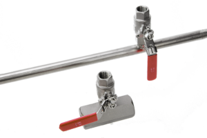
Measuring sections for precise measurements
Measuring section made of stainless steel 1.4301 incl. ball valve, up to DN 65 (R2 1/2“) with external thread, from DN 80 with weld neck flange according to DIN 2633.
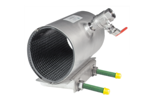
Spot drilling collars
If there is no measuring site with 1/2“ ball valve present it can be set up by means of spot drilling collars.
The spot drilling collar is imposed onto the pipe and tightened via thread rods. The enveloping rubber gasket is pressure-tight up to 10 bar. By means of the drilling jig it is possible to drill through the 1/2“ ball valve into the existing pipe.
Important: Please indicate the exact outer diameter of the existing pipe when placing the order resp. please select the suitable spot drilling collar from the adjoining list.
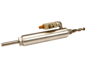
Drilling Jig
Drilling jig for set up a measuring site
Ideal for drilling under pressure. By means of a special drilling device a measuring site with 1/2“ ball valve can be easily set up within a few minutes. As an alternative to the welding of the 1/2“ fitting also a spot drilling collar can be used.

High-pressure protection
The supplementary device “high-pressure protection” serves for a safe installation and fastening of the CS sensors VA 5xx under pressure. It is strongly recommended to be used for gas or air pressures from 10 bar.
Mounting of the device
- Set up measuring site with screw neck (G 1/2″ outer diameter) according to the mounting instruction of the sensor VA 500
- Screw on the high pressure rig pressure-tightly and make sure that the ball valve can be opened and closed
- Close ball valve before mounting the sensor
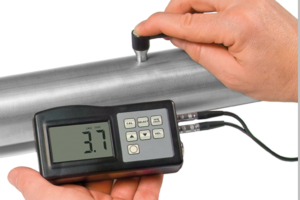
Thickness meter CS 0495
Enables a quick, easy and accurate measurement of the wall thickness of pipes. So the determination of the inner diameter becomes very easy.
Delivery includes:
- Case
- Calibration block
The thickness meter is small in size, light in weight, easy to carry. Although complex and advanced, it is convenient to use and operate. Its ruggedness will allow many years of use if proper operating techniques are followed.
